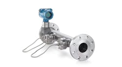
The ISO method for orifice design and calibration [1] is grounded in the ideal square-root relation between pressure drop and flow rate; specifies the in-pipe structure for an orifice; and corrects the nonideal relation with empirical relations. Unfortunately, for the empirical correction, the complexity of the 28-coefficient Reader-Harris/Gallagher equation and the eight-coefficient expansibility relation add potential for implementation error. Further, in many applications, the structure of the device or piping can't meet ideal specifications.
Of course, for official and legal situations, you should use the methods for orifice calibration as indicated by standards. However, engineering practice desires to minimize complexity. Accordingly, for internal use, you might find that relaxing the square-root basis provides a power-law relation that's much simpler and just as accurate [2]. Further, it doesn't require the piping structure that seeks to create near ideal up- and down-stream conditions, easing installation design constraints. However, it does require application-specific calibration.
Orifice essentials
An orifice is a one-point restriction in a flow line. It's commonly a disk with a hole in the center. The disk blocks the flow, all of which must squeeze through the hole. The high fluid velocity in the low diameter area reduces the pressure relative to the larger diameter upstream entrance section. The higher the flow rate, the greater is the pressure difference.
Since pressure difference is easy to measure, and since orifice assemblies are inexpensive to make and easy to adjust, orifice flow measurement is very common. In the following analysis, the pipe diameter is indicated by D and the orifice diameter by d0.
Analysis of the orifice flow rate-to-pressure drop relation typically starts with the Bernoulli equation, which is idealized for potential flow conditions (inviscid, constant density, isothermal, no lost work) along a streamline. Commonly derived as an undergraduate exercise, one form of the resulting orifice equation is:
(1)Where β = d0/D, and a is a combination of the several constants for a particular application.
The “hole” however, could be any number of shapes, or it could have an eccentric location, both features to permit entrapped gases or solids to pass through. Further, actual devices have many other features, such as piping flanges and pressure taps at various locations. Further, turbulent flow does not have the ideal flat profile that leads to the classic square root relation. Note also that the points of pressure measurement are not where the flow has an effective diameter of either D and d0. At the upstream pressure tap, the flow begins converging into the orifice, and has a smaller effective flow area than D would indicate. And the flow continues to converge as it exits the orifice, so the effective flow diameter at the downstream pressure tap is less than d0.
These realities are dismissed in the conventional orifice equations, and a generally accepted correction to the ideal relation is:
(2)
Where ρ1 is the upstream density, and CD is a factor to correct for both fluid flow and assembly geometric nonidealities. CD has a characteristic value of 0.62, for high Reynolds number situations. And, is a factor to correct for fluid compressibility effects. Both correction factors are empirical. The standard CD relation uses flow rate (Reynolds number), so the calculated flow rate is required to calculate the CD value needed to calculate the flow rate. Accordingly, obtaining Q̇ from Equation (2) requires an iterative calculation procedure.
That is an undesired complexity.
Further, the physical design of many orifice applications is not compliant to ISO standards. These include process installations without flow conditioners, without adequate upstream run, with pipes of less than about 2-in. diameter or integral orifice assemblies, such as flow devices on equipment and those used in pilot-scale applications. Without compliant geometries and installation, the standard equations don't provide accurate results. Providing an accurate calibration equation for non-compliant devices will improve their utility.
Power-law proposal
Considering these issues, we find that a power-law relation provides an excellent and much simpler fit of the actual flow rate with respect to differential pressure. Accepting that the transmitted signal from an orifice differential pressure transducer, such as 4-20 mA, is linearly proportional to ΔΡ and that geometric factors are fixed for a specific installation, there's a convenience associated with combining all coefficients into one constant and representing ΔΡ with the scaled signal, such as i – i0. This reduces the power-law orifice calibration equation to:
(3)
Here, i is the transmitted mA signal, and i0 is the mA value at zero flow rate.
Note that Equation (3) is equivalent to the ideal Equation (1), but with an extra coefficient to account for the nonideality of fluid and device. The values for the a and b coefficients will be determined empirically to best fit experimental data.
Note that the value for the coefficient b should be close to the ideal 0.5, and that coefficient a should have a value close to the expected:
where ΔΡmax is the ΔΡ range that corresponds to the 4-20 mA signal, and 16 is the range of the 4-20 mA signal.
For devices where off-line or even in-line calibration is possible to determine values of coefficients a and b, Equation (3) specifies a direct, not iterative, calculation. It's simple to understand. With little complexity and few coefficient values, it reduces the opportunity for implementation errors in equation transcription, unit consistency and coefficient value transcription.
Proven by experiment
The ISA Transactions article [2] provides experimental evidence for the utility and precision of Equation (3), using both pilot-scale experiments and the database that was used to generate the CD and ε relations [3]. Coefficient values were obtained by a best fit of model to the data. Although a linearizing log-transform can convert this nonlinear regression exercise into a simpler linear regression, linearization distorts the relative importance of high-range and low-range data [4]. Accordingly, the power-law study used nonlinear regression to determine coefficients a and b for Equation (3) to best fit the data.
On a range of liquid and gas applications, the values of power b vary from 0.4858 to 0.5255 for our experimental air and water tests on the pilot-scale devices, and from 0.4887 to 0.4943 on the NIST database (flanged orifice types, compliant geometries and fluids that included water, gas oil, nitrogen gas and natural gas). Further, if the square-root functionality, b = 0.5000 is presumed, then the CD correction should express a functionality that has the complementary power (for instance 0.5000 - 0.4887 = 0.0113), which we found it does.
The accuracy and precision of Equations (2) and (3) were also compared. Accuracy is a measure of the model closeness of fit to the data, which can be indicated by any of several measures. In all of 10 cases investigated, the flow rate accuracy of Equation (3) was better than either Equation (1) or Equation (2).
[javascriptSnippet]
Precision of the equations was assessed by a propagation of variance, which relates uncertainty on an input to the uncertainty of the calculated flow rate. The relative uncertainty values for the power-law model are lower than those for the ISO standard model. Further, they indicate that the power-law model proposed here will be useful over a wider range.
Parameters and limitations
Even with the improved accuracy of the power-law model, orifice meters are not as accurate as some other flowmeter types. Best expectations cite a 2% error. If measurement accuracy and range are critical, another flowmeter type will likely outperform the orifice.
The power-law calibration procedure (to experimentally get values for two coefficients) requires calibration data that's specific for the device, whereas using an ISO-compliant device will rely on standard equations. A case-by-case analysis is required to determine if the accuracy benefit and device geometry convenience are worth the calibration effort.
The calibration of the two-parameter Equation (3) does require at least two experimental data points. However, experimental noise will bias the coefficients. The accuracy and precision of this study was achieved with 15 or more experimental data sets throughout the operating range. However, such extensive calibration testing may not be desirable. If accuracy is important, use another flow metering device. If operational convenience is important, then the two-point calibration may be adequate.
The computational device you're going to use might not have the ability to compute a power-law.
Noise on the i value in Equation (3) and/or calibration drift on the i0 value could result in the quantity (I – i0) having a negative value at very low or zero flow rates. To prevent an execution error, add a conditional to reset (I – i0) to zero if it is negative.
Replacing the standard equations with a power law require a case-by-case analysis of the infrastructure surrounding the orifice technology and practice (maintenance, training, manuals, computer software, data acquisition hardware, etc).
For many industrial applications, in-line or off-line calibration testing is not practicable or compliance to standards is important. For these, compliance to the appropriate standard remains as best practice.
In conclusion, where flow conditions and assemblies don't approach ISO-compliant attributes, where off-line or in-line calibration is applicable and where the measurements are for internal use, my investigations find the power-law approach matches the nonideal fluid and device attributes, and offers advantages of calculational simplicity, precision, accuracy and rangeability over the use of the ideal square-root model.
References
- ISO 5167, “Measurement of fluid flow by means of pressure differential devices inserted in circular cross-section conduits running full,” International Standard 5167, Parts 1 and 2, 2nd Edition, the International Organization for Standardization, Geneva, Switzerland, 2003.
- Rhinehart, R. R., S. Gebreyohannes, U. Manimegalai Sridhar, A. Patrachari, and MD Rahaman “A Power-Law Approach to Orifice Flow Rate Calibration,” ISA Transactions, Vol. 50, No. 2, pp. 329-341, 2011.
- U.S. Dept. of Commerce, NIST Standard Reverence Database 45, “GRI/NIST Orifice Meter Discharge Coefficient Database,” Version 1.0, NIST (National Institute of Standards and Technology), Gaithersburg, Maryland, USA, 1994.
- Rhinehart, R. R., Nonlinear Regression Modeling for Engineering Applications: Modeling, Model Validation, and Enabling Design of Experiments, Wiley, New York, NY, 2016.


