Q1: At the last meeting of my ISA chapter, I was told that by using "valve position control,” I can design load-following optimization and save energy in many processes. I didn't completely understand how it works. Could you please explain it? Thank you.
Z. Friedmann
[email protected]
A1: This is a large topic. In my handbook, you'll find more than 100 pages discussing it. You're right that it can be a powerful tool to optimize operating capacity, efficiency or energy costs. Valve position control (VPC) can also be implemented in a couple hours, as it is one of the simplest methods of optimization, but it can also do a lot of harm if misapplied. Therefore, it's essential to fully understand the nature and dynamics of the process that one intends to optimize with it. For this reason, it's worth spending a couple of hours, sitting down with the process engineers and the operators, to gain a full understanding of the potential consequences of using it. Below, I'll briefly describe a few common applications to illustrate the concept.
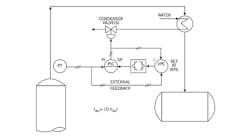
Distillation (Figure 1A): Using VPC to minimize the operating pressure of a total condenser system used in distillation applications reduces heat input, increases reboiler capacity and reduces reboiler fouling. VPC achieves this by continuously maximizing cooling by keeping the pressure control valve near its full opening, and thereby keeping the condenser fully loaded. This being a cascade loop—where the slave should be 10 times faster than the master—proportional and integral (PI) actions are used in the controller (PIC) and integral action only in the VPC. This integral is set for about 10 times the integral in the PIC. The external reset is provided to protect against reset windup, when one of the limits that block the VPC output is reached. These limits are provided to keep the range within which the column pressure can be floated by the VPC within safe limits.
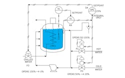
Reactor (Figure 1B): In the illustrated reactor control system, the VPC serves to minimize the cost of cooling by sending the chilled water to a separate chilled water coil only when the regular cooling water valve to the jacket is fully open. Here the VPC keeps the more expensive chilled water valve closed until the cooling capacity of the less expensive cold water is fully exhausted. The cascade temperature loop operates in a split-range fashion, so that at a temperature controller (TC) output of 0%, the cooling is maximum (both chilled and cooling water valves are fully open); at 25%, the chilled water valve is closed, but the regular cooling water valve is still fully open; at 50%, both cooling valves are closed and the heating valve just starts to open; and finally at 100%, the reactor receives full heating through the full opening of the hot water valve. Naturally, one can overlap the transition points, which improves control, but does it at the cost of lowering energy efficiency. For smooth operation, the fact that there are three control valves should be transparent to the temperature controllers because the valve gains should be the same and their combined range should provide a straight line.
Figure 1B: In this reactor coolant application, the cost of cooling is minimized by minimizing the use of the more expensive coolant. (FO = fail open, DA = direct acting, RA = reverse acting)
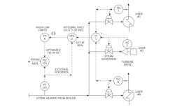
Boiler (Figure 1C): When a boiler serves several steam users, the VPC-2 (set at 80% or 90%) opens all user valves until the most open one is at a full opening setpoint. The VPC in turn reduces the setpoint of its cascade slave, the steam pressure controller (PIC). This cuts operating costs because it reduces the power consumption of the boiler feedwater pump, and increases turbine drive efficiencies by opening up their steam governors. In addition, the VPC protects all users from running out of steam, moves all valves away from the near-closed and therefore unstable positions, and reduces maintenance and increases valve life by lowering their pressure drops. Otherwise, the control system is similar to all VPC systems, where a high selector sends the measurement of the opening of the most open valve to the VPC, which is an integral only controller (its integral setting is 10 times that of the PIC), plus has an external feedback against reset windup. The VPC output to the PIC setpoint is limited to a range to match the limitations of the controlled equipment.
Figure 1C: Meeting steam demand of the plant with minimum steam pressure increases efficiency.
Cooling towers (figure not shown): The energy consumption (cost of operation) of cooling towers can be minimized by keeping the most open user-inlet valve and the most open cooling-water-return valve nearly full open. This minimizes the cost of circulating water in the plant by minimizing the pressure drops through all the cooling water valves. The fan speeds are controlled by the required cooling water supply temperature of the plant in such a way that even the highest speed will be under the maximum.
Water balancing is controlled by measuring the total return flow, which becomes the setpoint for the flow-ratio controllers serving the three towers. The ratio setting of each controller can be set manually or automatically, and is based on the associated tower's capacities and fan status. Naturally, the total of the three ratio settings must always be 1.0.
The pumping costs associated with such a system will be minimized when the pressure drop through the three cooling tower supply valves is at a minimum. This is guaranteed by the VPC, which measures the opening of the most open valve and compares it to its setpoint, which is about 95%. As long as all valve openings are below 95%, the VPC increases all setpoints until the most open valve reaches 95% opening. This way, the return water distribution will be correct, plus both groups of valves (the user inlet and the tower inlet valves) will be operating at minimum pressure drop.
Béla Lipták
[email protected]
