Axial and centrifugal compressor control is exceptionally challenging due to the extraordinary speed and severity of problems, and the extreme consequences in terms of plant safety and performance. The fastest and most dangerous phenomenon is compressor surge. An axial or centrifugal compressor can reverse flow in 0.03 seconds, going from a large positive flow to a large negative flow. Often, the negative flow is not measurable by flowmeters, leaving the actual situation to your imagination. If you knew exactly what was happening, it would be even scarier, motivating you to seek greater understanding and prevention of the problems. Presently, we tend to rely on companies specializing in surge control to protect you and your plant, but what happens if something is not quite right in the middle of night, causing a surging fright and piping to take flight?
The author’s perspective
My goal has always been to develop a deeper understanding through plant experience and focused dynamic models. Developing a compressor model caused my career to shift from being the lead instrument and electrical (I&E) engineer to becoming part of a group of elite modeling and control specialists in an Engineering Technology department. The compressors were the source of air feed to the catalytic reactors in the world’s largest plant for a key monomer needed for nylon production. The compressors cost tens of millions of dollars, and any shutdown would cause millions of dollars a day in lost profits. Additionally, startup was the most dangerous and difficult mode, taking a day or more. A decade later, I worked on a special rotor for an axial compressor, which cost more than a million dollars. The plant only could afford to have a couple of spare rotors. Overspeed during surge could cause costly rotor failure.
The model was used in other plants to develop better compressor control and procedure automation to completely automate startups. In one plant, operators said startup could not be automated because it required too much expertise. The operators’ trial-and-error approach resulted in false starts, taking days to finally get online. I put the best operational procedure enhanced by deeper knowledge gained from modeling into one of the earliest versions of a virtual plant to test and demonstrate the results. When commissioned, the compressor automatically started up in a matter of minutes. The repeatability of the startup also enabled changes in compressor performance and operating conditions to be analyzed.
My goal throughout my career is to develop deep fundamental knowledge based on principles, models and plant experience, sharing the results through presentations and publications. I was encouraged to do so in Engineering Technology, then in Research and Development for the past 40 years. In a way, my path was similar to that of Greg Shinskey, whose many publications were my key source of greater understanding (as discussed with his protégé Sigifredo Nino in the Control feature article, “The greatest source of process control knowledge,” October ’17, p. 49).
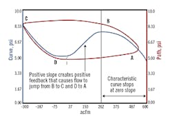
Figure 1: At point B, where the compressor characteristic curve slope is zero, the operating point jumps to point C. The precipitous drop in pressure signals the start of the surge cycle and flow reversal (negative ACFM). As the plenum volume is emptied, the operating point follows the curve from point C to point D, where the slope is again zero, and then jumps to point A.
The resulting concepts from deep knowledge eliminate many misconceptions in our profession that often lead to thinking every particular application is special and any solution must be simply duplicated. Such misconceptions trigger copy jobs and proliferate systems that have unrealized fundamental limitations. These unrealized problems can surface and threaten plant safety and performance. It is upsetting to me (and the plant) that deeper knowledge is not sought, and the incredible new flexibility and capability of today’s instruments and controls is not extensively utilized. The perceived value of our profession is in dire straits. Just ask your management what they think you, as automation professional, bring to the party.
Understanding compressor surge
The surge point on the compressor map (typically a plot of compressor pressure rise versus suction flow) is the point where the slope of the characteristic curve becomes zero. Each characteristic curve corresponds to a particular speed or inlet guide vane position. Plot 2 in Figure 1 shows the compressor characteristic curve seen and unseen. Compressor manufacturers often don’t show the compressor characteristic curve to the left of the surge point, creating a mystery and vulnerability.
A first-principle model has provided the knowledge of how negative and positive feedback occurs from the sign and magnitude of slopes seen and unseen in the compressor characteristic curve. The negative slope of the curve to the right of the surge point provides some negative feedback to help with stability. As the flow decreases, the pressure rise increases, creating a greater downstream valve pressure drop and possibly flow. If the downstream valve position continues to decrease, the operating point proceeds to walk to the left from point A along the characteristic curve. When the operating point reaches the zero-slope point, it jumps in about 0.03 seconds to a negative flow, signifying the beginning of the surge cycle.
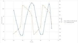
Figure 2: Discharge pressure and suction flow oscillations for a compressor in severe surge. If a surge valve is not opened, the process of Figure 1 repeats, resulting in oscillations. The jumps in suction flow measurement between peaks and valleys are not seen in pressure measurements due to smoothing by suction and header volumes, but are disruptive and damaging due to high axial thrust and radial vibration.
It’s kind of like walking up a mountain, then falling off a cliff. The compressor characteristic curve to the left of the surge point creates a total characteristic curve that looks like a sine wave, as seen in Figure 1. The positive slope immediately to the left of the surge point (maximum compressor pressure rise) creates positive feedback that causes the operating point to jump from point B to point C, the start of the negative slope. The operating point walks along the negative slope from C to D, the point of zero slope (minimum compressor pressure rise), and then jumps to the right back to the starting point A. If a surge valve is not opened, the process repeats itself, resulting in the oscillations seen in Figure 2. Note the jumps in the suction flow measurement between peaks and valleys are not seen in pressure measurements due to the smoothing by suction and header volumes.
The jumps are highly disruptive and damaging due to high axial thrust and radial vibration. Surge cycles damage bearings and decrease efficiency with each cycle. For axial compressors, the damage may be measureable after a few surge cycles. The total number of surge cycles provides a good metric of the total loss in compressor efficiency. It is imperative to prevent the surge and to ensure sustained recovery.
Surge setpoint
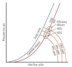
The surge controller setpoint should be offset to the right of the surge curve on the compressor map, as shown in Figure 3. If the surge setpoint follows the shape of surge curve, the offset can be optimized to be on the longitudinal axis of the efficiency ellipses. The size of the offset depends on the speed of the automation system and the tuning of the surge controller. Some plants may think of the surge curve as being the point where the surge valve opens. In this case, integral action must be greater than the proportional action. However, the extra integral action causes a larger overshoot of the surge setpoint, necessitating the setpoint offset to be increased accordingly, which generally corresponds to lower operating efficiency.
Figure 3: The optimum surge setpoint follows the shape of the surge curve with an offset to intersect longitudinal efficiency ellipses. The offset is large enough to prevent surge.
Most other plants see the surge setpoint as being the best operating point, when surge valves are open through tuning so that proportional action dominates integral action, preventing overshoot. Using higher controller gain rather than a lower reset time gives a faster correction. Whether an automation system can achieve this depends on attention to the surge valve’s 86% response time, transmitter update rate and damping setting, and controller scan time and execution rate. In general, the summation of the valve response time, transmitter damping and ½ of each update rate, scan time and execution rate must be less than 2 seconds. For closer operation to the surge curve and to reduce dire consequences from surge, the total must be less than 1 second. How fast the automation system really needs to be and the required tuning of the surge controller is best determined by running a first-principle dynamic model that includes a momentum balance as well as material and energy balances. A word of caution here is that some I/O scan rates may be much slower than the fastest controller execution rate.
Surge control system
Even a fast feedback controller is unable to get a compressor out of severe surge because of the huge jumps in flow. What is needed is an open-loop back up that forces the surge valves to immediately open and holds them open for sufficient time to sustain operating point stability before allowing the feedback controller to start to close the surge valves. The open-loop backup is triggered by a large predicted overshoot of the surge setpoint to prevent surge, or a precipitous drop in flow indicating an actual surge.
An innovation uses a predicted overshoot via a fast future value that is generated by the rate of change of a decreasing flow, with a good signal-to-noise ratio multiplied by the total loop dead time, with updates every controller execution. The open-loop backup simply puts the feedback controller into a remote output mode that is seen by operators. The remote output is immediately stepped up to a position that typically prevents surge, but is incremented every execution until the future value stabilizes, putting the surge controller bumplessly back in cascade with the surge setpoint computed to sustain an offset from the surge curve. Many suppliers of standalone compressor controllers have proprietary control strategies providing feedback control, with a backup requiring special expertise and tuning.
External-reset feedback (ERF), also known as dynamic reset limit, in the surge controller, with a fast readback of actual valve position, enables up and down setpoint rate limits in the analog output blocks to provide fast opening and slow closing of the surge valves without the need to retune the surge controller. ERF can also eliminate oscillations from valve resolution and sensitivity limits (as seen in the Control feature article, “How to specify valves and positioners that don’t compromise control,” March ’16, p. 39).
The surge control system principles basically are the same for surge vent valves and surge recycle valves. At least two valves in parallel are used to provide redundancy, particularly because surge valves might not open after sustained operation in closed position, where stiction from seal or seat friction is greatest. For multiple stages, there generally are recycle surge valves and a compressor surge control system for each stage. Ratio dividing may be used to proportion the different pressure rises for each stage.
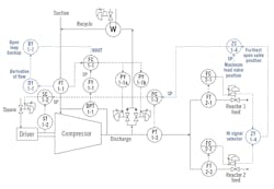
Figure 4 shows the surge control system with recycle surge valves and two downstream users feeding reactors. Many systems have more reactors. A valve position controller can minimize the pressure setpoint to increase compressor efficiency by pushing a user valve to the maximum effective throttle position (e.g., 60%). The valve position controller has external reset feedback with setpoint rate limits on the compressor pressure controller to provide a gradual, smooth optimization with a fast getaway for a disruption.
Not shown in Figure 4 is feedforward action to deal with the fast closing of user valves. What may seem to be a slow enough closing of a user valve can be troublesome because of the quick opening characteristic of on-off valves triggered by safety instrumented systems, where nearly all of the flow change occurs within 10% of closed position. The feedback and feedforward signals must be linearized based on the installed flow characteristics of the surge valves and user valves, respectively. If a high-rangeability, fast and reliable user flow measurement is used for the feedforward, the characterization of the feedforward signal for the feedforward summery is unnecessary. Much more detail, with a focus on practical essentials, is offered in the book Centrifugal and Axial Compressor Control.
Figure 4: The surge flow controller FC1-1 and enhanced PID valve position controller ZC1-4 have external reset feedback for directional move suppression for fast opening with slow closing of surge valves for fast getaway in abnormal situations and gradual optimization. The derivative of the suction flow computed by DY1-1 uses a deadtime block to provide immediate updates. This derivative can be multiplied by the deadtime and added to the current suction flow to predict flow one deadtime into the future. Each reactor feed valve position can be used to provide a feedforward signal.
In Figure 4, the derivative of the suction flow computed by DY1-1 uses a deadtime block to provide immediate updates with good signal-to-noise ratio. This derivative can be multiplied by the deadtime and added to the current suction flow to give a predicted flow one deadtime into the future. This plus reactor feed valve position can be used to provide a feedforward signal to help surge control deal with user (i.e. reactor) shutdown.
The same type of calculation used to give a future value can be used to find and document surge points on the surge curve on the compressor map. Detecting a nearly zero rate of change in pressure for a change in suction flow indicates a surge point. Detecting a severe rate of change of suction flow indicates a surge cycle, with extreme negative rate of change signifying the beginning and an extreme positive rate of change signifying the end of each surge cycle. Future values can be computed with a good signal-to-noise ratio and preemptive corrections (as noted in the Control Talk blog, “Future PV values are the future”).
Compressor model
Deeper understanding of compressor surge control, the dynamic requirements of the automation system, setpoint optimization, surge control system design with future values, and surge curve identification is best achieved by using a virtual plant (digital twin) with a complete compressor model. This digital twin can generate all of the plots in this article and give much more. This knowledge is nearly impossible to obtain elsewhere and is essential for preventing compressor damage, loss of compressor efficiency, shutdowns and hazardous operation of downstream exothermic reactors.
The compressor models seen in industry to date critically lack the momentum balance needed to show the path, and to include the normally unseen compressor characteristic curve to the left of the surge point. The momentum balance incorporated into the digital twin, which is the basis of this article, is developed from innovative research documented by E. M. Greitzer in “The Stability of Pumping Systems—The 1980 Freeman Scholar Lecture” (Journal of Fluids Engineering, June ’81, p. 193–242) and subsequently confirmed through testing by K.E. Hansen et al. in “Experimental and Theoretical Study of Surge in a Small Centrifugal Compressor” (Journal of Fluids Engineering, September 1981, p. 391–395).
By having the much more complete model in a virtual plant, the true dynamic behavior of the system can be investigated and the best control system performance achieved by exploring, discovering, prototyping, testing, tuning, justifying, deploying, commissioning, maintaining and continuously improving as described in the Control feature article, “Virtual plant virtuosity” (August ’17, p. 40).
The surge model results and automation system requirements are also described in the previously mentioned book, Centrifugal and Axial Compressor Control. Additional guidance and a video demo are available here.
Invest some of your own time to see the future of a synergy between modeling and control. Use the model to learn what is truly important and what is really needed. By employing the model in a digital twin, you can take advantage of the incredible flexibility and capability of today’s control systems. Don’t take a back seat but instead, seek to provide the leadership to show what you and our profession can do to make plants safer and more productive.
Greg McMillan, Control columnist, can be reached at [email protected]. Chris Stuart, software engineer, R&D/Engineering and Thomas Hildebrand, simulation engineer 1, Systems/Project Engineering, at Emerson Automation Solutions, can be reached at [email protected] and [email protected].

