This column is moderated by Béla Lipták, automation and safety consultant and editor of the Instrument and Automation Engineers' Handbook (IAEH). If you have an automation-related question for this column, write to [email protected].
Q: I am an energy engineer currently looking at optimizing the pumping circuits in process plants by reducing unnecessary pressure drop across the system. Please advise me on my understanding. Your handbook, Volume 2, Chapter 6, ”Control Valve Selection and Sizing,” says, "The proper approach to the selection of valve pressure drop is to first determine the total friction energy loss (excluding static energy) of the system at normal flow, and assign 50% of that to valve pressure drop." In your view, during the new pumping hydraulic circuit design/new pump sizing, what is the recommended percentage of differential pressure (DP) across control valve to the total system pressure drop (i.e. including control valve DP)? In your opinion, at the design stage, what are the recommended rules of thumb (the percent of control valve DP of the total system DP) that one can apply in the real process operation?
Seer Ping
[email protected]
A: There is more to pumping system optimization than assigning the right DP to a control valve, which you can read about in my book, "Optimization of Industrial Processes."
Flow can be controlled either by reducing the driving force of the fluid (slowing the pump) or by artificially increasing the system resistance to flow (friction) and burning up some of the pumping energy by throttling a valve. If you had some good reason to use a valve, you could size it by assigning it 25-30% of the friction drop at 75% flow coefficient (Cv), but if your goal was to minimize the energy cost of running the system, you should consider using a variable-speed pump.
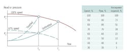
Speed throttling saves the energy that valve throttling would have wasted. The saving by variable-speed pumping increases as the system head curve becomes steeper. Figure 1 shows that as the flow drops from F1 to F2, the percent of the pump speed (100% to 67%) and horsepower required drops faster. Energy savings also increase as the system curve gets steeper, because the friction drop (Hf) portion of the total system drop (Hs) increases. The higher the Hf/Hs ratio (friction drop divided by total system pressure drop), the more justifiable the use of variable-speed pumps.
Figure 1: In variable-speed operation, when flow is to be reduced from F1 to F2, instead of wasting the pumping energy (P1-P2), the pump speed is lowered from 100% to 67%.
The total efficiency of variable-speed pump installations is determined as:
SEI = (Ep x Em x Ev x Eu)10-6
Where:
SEI = System efficiency index
Ep = Pump efficiency (%)
Em = Motor efficiency (%)
Ev = Variable=speed drive efficiency (%)
Eu = Efficiency of utilization (%)
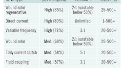
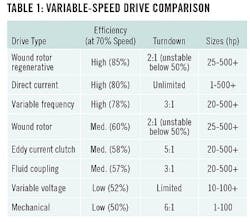
The introduction of the pulse-width modulated (PWM) adjustable-speed drives with sensorless flux-vector control has brought adjustable-speed pumping into the mainstream of everyday applications. Once all four efficiencies are determined, they can be represented by a single system efficiency index curve. Table 1 provides a summary of some of the main features of the various variable-speed drive designs.
Béla Lipták
[email protected]
A: In my view, the proper answer has changed a bit with the technology. I don’t disagree with Bela but if the flows are considerable and the energy cost is significant, the cost spent in a more thorough study might be justified.
Please bear in mind that that the valve provides only the required pressure drop, valve selection sets the minimum pressure drop and the flow step size, and the control system sets the valve position. An important question to ask is, what are you willing to pay for a better valve in order to install a smaller pump or reduce other pressure loses? The dynamic response of the valve sets the excess pressure required from the pump. Even piping size may be involved.
When selecting a valve, remember that every control valve has friction to overcome before the valve stem moves and changes the pressure drop across it. A valve with 10% or worse ''dead band" (and this is not unknown) means that a considerable excess pressure drop is required. Even 1% dead band will result in notable control cycling if there is any capacitance (integrating function) or any lost time in the control loop. The larger the control valve maximum Cv, the less open the valve will be at normal conditions, and therefore the step size in flow is larger and less certain.
It is possible to specify maximum dead band in the purchase specs. All this is described in ISA-TR75.25.02-2000 (R2010) - Control Valve Response Measurement from Step Inputs (disclaimer: I chaired the subcommittee). It all comes down to money. Save money in construction costs and you might add costs for the life of the project. Design time costs money now, energy costs are monthly. Good engineering is a good investment. Even a simple simulation or a spreadsheet analysis might aid in the decision.
Cullen Langford P.E.
[email protected]
A: If wanting to minimize pumping energy, the optimum valve would be one with minimum pressure loss, a large Cv. But this would mean that the flow rate response to valve position (controller output) would be nonlinear. Even with the linearizing effect of an equal-percentage valve characteristic, a valve with minimal pressure losses would have a nonlinear control variable (CV) to manipulated variable (MV) response. It would present a tuning aggravation that would need some sort of gain scheduling or output transformation to temper it. So, the classic choice of a valve is a compromise to have a higher, but tolerable, pressure drop to have a somewhat linear convenience for the controller. That is one issue.
There is another – excess capacity. Conceptually, knowing the desired flow rate and the pressure losses from the piping characteristics, one could choose a pump to exactly match that line’s flow losses and flow rate specification. Choose a pump with zero excess DP to minimize pumping expenses. But that pump would not have excess power, and it could not compensate for things that increase line pressure losses (in-line silt, blinding things on the screens, erosion/corrosion-induced surface roughness, half-opened valves, bypass arrangements, temperature and composition changes in viscosity or density, etc.). Further, the nominal steady-state designed flow rate may need to be exceeded for rapidly filling or emptying a tank.
Traditional heuristics for valve sizing increase the pump size (and operating expenses), but provide that safety factor excess for the many reasons. There are many rules of thumb for valve design to permit operability at a not-too-excessive DP. I’ve championed this one: Use an equal-percentage valve characteristic. Set the valve Cv so that when the valve is 70% open it can handle the nominal flow rate with a valve pressure drop equal to 30% of the friction losses in the piping system (exclude elevation and inlet and outlet pressure effects). This does create an undesired pressure drop under nominal conditions, but creates a linear-ish control response and excess capacity. Many alternate heuristics are equivalently good.
A valve is a flow restriction. If the flow is ideally turbulent and the valve does not change position, then if something else makes the flow rate change, the DP across the stationary valve will scale with the square of the flow rate. Decreasing flow rate will decrease the pressure drop. If, however, the valve stem is changed to reduce the flow rate, then the pressure drop across the valve will increase. Ideally, consider that the pump DP remains unchanged—then the lower flow through the piping system will lead to lower friction losses. To create the lower flow, the valve DP must be the difference between the pump and the line flow losses.
R. Russell Rhinehart
[email protected]
A: A reader asked me why people still use control valves instead of the much more energy-efficient speed-controlled pumps. My answer was: The so-called energy efficiency is mostly a myth. Manufacturers use this claim in their misleading advertisings and fancy graphs. However, their claim is solely based on measuring the power consumption of the pump's motor and completely omitting the equally power-hungry device that regulates the voltage or current to the pump motor. Please consider this: If, in a system, the kinetic energy of a flowing mass is reduced (say by pressure reduction), this energy change can be measured in kW. Now, it makes no difference if the energy change is done by a valve or a speed-controlled pump, there has to be an equal amount of energy consumed in order to match the power change in the system. This is dictated by the laws of thermodynamics.
People try to disobey this law, but they always fail. I hope you like my explanation. In order to acheive power balance, the control valve does it trhrough turbulence, the speed pump by changing the flow rate.
Here are 2 true stories:
1. Not too long ago, a major company debated whether to replace control valves with s.c..pumps. As their consultant, I advised against it. To stop the debate, management ordered a test using 2 parallel loops. One using a control valve the other a s.c.pump. The first test run prooved embarrassing to me. So, I asked the tester, where did he measured the power. At the cable to the motor, of course. I gently advised to put the clamp on the cable to the rectifier instead. Sure enough, my honor was saved. The project was canceled.
2. In the late 70ties, Exxon-Mobile Co., due to my influence, divested themselves from a recently acquired expensive sc.co.. pump company. The idea was to save millions in power cost. Unfortunately, it did not worked out that way, thanks to one of my article proving no or little energy savings.
Speed controlled pumps have one advantage: They can also increase pressure, a feat, control valve cannot.
Hans Baumann
[email protected]


